Events
What is an event?
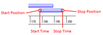
An “event” is a device (servo, motor, relay, etc.) action. Essentially, you tell the device how much to move, when to start moving, and over what period of time to move. To do this, VSA needs four pieces of information: start time, stop time, start position, and stop position.
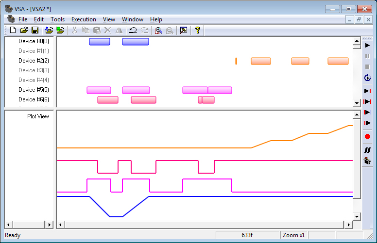
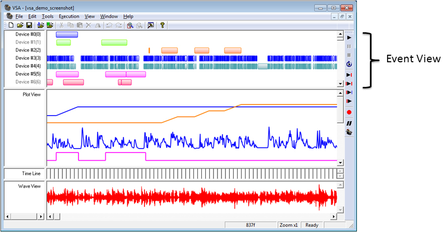
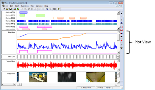
When VSA encounters a Linear Bar (see Editing event properties) event during playback, it interpolates between the start and stop positions to create a smooth motion. An event, then, is a speed (change in position/change in time). Imagine that you have an event with a start time of 10, a stop time of 20, a start position of 127, and a stop position of 147. ; Since there are 10 frames and 20 steps in position, VSA will move the servo two steps every frame for 10 frames. Tracks 0 and 2 (blue and orange), shown below, demonstrate Linear Bars: notice how the positions during an event are interpolated and the positions between events remains fixed. A Pulse Bar (see Editing event properties) is used for relays and commands the relay to an on value at the start of the event and an off value at the end of the event. Tracks 5 and 6 (red and pink), shown below, demonstrate Pulse Bars: notice how the Plot view shows that the positions are pulsed to the appropriate values when the events are encountered.
Note: The start position is actually defined by the last position of the device (which is the stop position of the previous event).
Note: Events in a normal (error free) state are entirely the color selected in the Device Settings dialog. When selected (see Selecting events), events are highlighted in green; when an event contains an error (see Logical design check errors, the event is highlighted in red.
Creating events
Event creation is a simple drag operation. With the mouse cursor in the Event view, left click and hold to begin creating an event. A black outline will appear showing the proposed event. As you continue to hold, drag the mouse and the outline will expand and contract to follow the mouse. Notice how the event was created for the track beneath the cursor when the drag started. When the event is of the desired time span, release the left button to end the drag operation; a new event is created.

Dragging can also be used to scale and size existing events and groups of events (see Sizing & Scaling Groups of Events).
Editing event properties
There are four pieces of information associated with a device: start time, stop time, start position, and stop position (see What is an event?). The start and stop times are most easily edited by visually adjusting the events. (See Working with events.) Furthermore, the start position is always defined by the last commanded position to the device (i.e., the stop position of the most previous event).
Event type
The event type describes how the event is translated into movement. A Linear Bar interpolates between the start and stop positions smoothly over the start and stop times. Linear Bars are often used for motors and servos. A Pulse Bar simply sets its value to the pulse value during the duration of the event. Pulse Bars are typically used for relay devices (e.g., the relay should be on; everywhere there is a Pulse Bar).
Start and stop times
The event’s times may be modified by simply entering alternate values in either frames or a MM:SS format (see Modifying the time display).
Start and stop positions
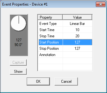
Start and stop positions are only available for Linear Bar servo-style events. The start position is defined by the stop position of the most previous event (for the first event, the start position is the default value). The stop position may be changed in a variety of ways. First, the stop position may simply be entered in the corresponding text box. Second, the stop position may be determined by a guess-and-check method. Often times, servo and motor values do not have any “real” meaning. While a position of 127 may correspond to a servo arm position of 180°, it may not correspond to a movement of 180° of a robot’s elbow, for example. Knowing the correct value to enter can be difficult, if not impossible, and every system is different.
The darkened box in the “Control” panel represents the servo, motor, or dimmer.
The SMI motor device (left) depicts the speed of the motor. Left drag the speedometer arm to adjust the motor speed. The servo device (middle) illustrates the position of the servo. Left drag on the servo arm to move the servo. The dimmer device (right) represents the brightness of the lamp. Left drag the knob to adjust the value. As you drag the speedometer, arm, or knob, the actual device will show this newly chosen position.
When you have moved the servo to the desired stop position, the “Capture” button copies the servo’s current position to the “Stop Position” text box. The servo will now move to the new position.
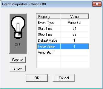
Default and pulse values
Default and pulse values are available only for Pulse Bar relay-style events. The default value typically represents the off state of the relay. The default value can only be set in the Device Settings and is sent at the end of the event. The Pulse Value is sent at the beginning of an event and typically represents the on state of the relay.
Annotation
Annotations provide a convenient means to associate events with real actions. By either modifying the event properties directly or by right clicking on a selected event(s) and choosing to Edit Notes…, the user may associate a text string with each event(s). By selecting several events, right clicking on one of the events, and choosing Edit Notes… several events can be given the same annotation.
The annotation text string is displayed in the status bar when the mouse is over the associated event. Annotations are also used during Analysis (Library Imports).
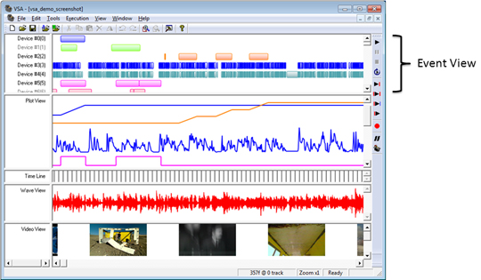
Event view
The Event View contains all the information for commanding the devices during execution. As the routine plays, device “events” are encountered (see What is an event?), and it is these events that contain the position of the particular device at a given time. The Event View and the Plot view represent the same event information, but in different ways. The Event View is useful for grouping and editing the duration of events, while the Plot View is useful for visualizing and adjusting device positions.
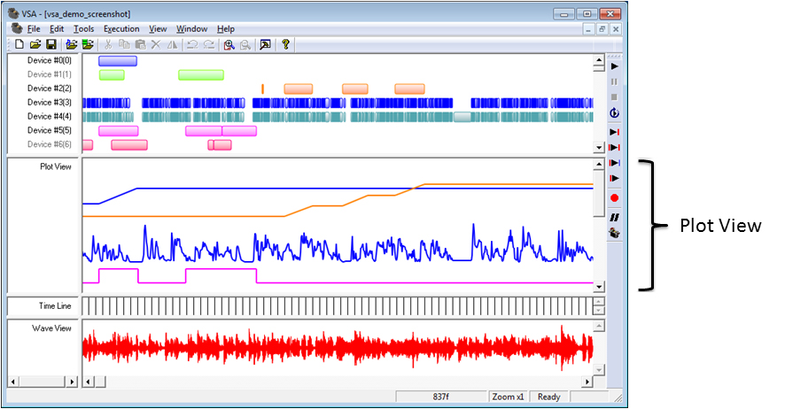
Plot view
The Plot View displays event position on the vertical axis and time on the horizontal axis. The Event view and the Plot View represent the same event (see What is an event?) information, but in different ways. While the Event View is useful for grouping and editing the duration of events, the Plot View is useful for visualizing and adjusting device positions.
Capturing events
Events can be captured in real-time. During a real-time capture sequence, tracks can be recorded while the other enabled tracks are replayed with the audio. This recording operation provides a quick means to capture a series of complex movements and then fine tune them with the editing capabilities of VSA. See Features for details on how many channels you can capture with your version of VSA.
To begin capturing events, select Capture Events from the Execution menu. The following dialog will be presented were recording options can be adjusted:
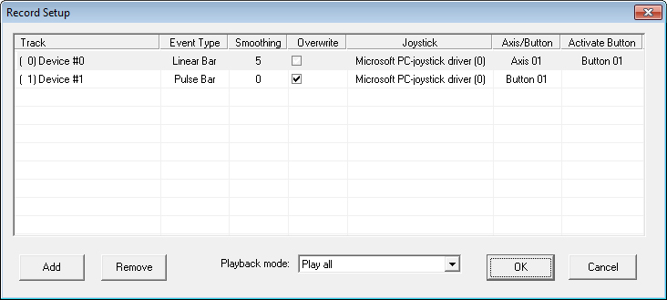
Add a track to be recored by pressing Add. The Event Type will be automatically selected based on the track type (relay or other).
Select the Smoothing parameter to adjust how VSA should filter (or smooth) the captured input before generating events (higher smoothing values will capture less detail, but will result in fewer events).
Check Overwrite if the events for the captured tracks during the playback time period should be deleted after capturing.
If one or more joysticks or KORG nanoKONTROL2s are installed, select the joystick. If recording a Linear Bar, select a joystick axis; otherwise, select a joystick button. The Activate Button will cause capture to occur only while the selected button is held down. Set this value to None if you want the axis to continuously capture.
Finally, select the Playback mode to determine the time period for capture.
Once you select OK, capturing will begin immediately. The device controls will be displayed in a small window. Use this control device to direct the motion for the capturing channel. The track must be enabled in Device Settings for the hardware to be commanded. Stop or Pause the playback at anytime.
Tips for Capturing
If the mouse control is cumbersome, try using a joystick or KORG nanoKONTROL2 to capture positions.
Especially for lip-sync operations, listen to the audio several times so that upcoming movements can be predicted and response will be timely. If you find that your response lags, simply drag the recorded events back into audio synchronization.
Joystick/MIDI control
You can also control the virtual device using a properly configured joystick or MIDI KORG nanoKONTROL2 while Editing event properties, for example.
If using a joystick, properly configure it in the Windows control panel joystick calibration facility. Determine which button is “Button #1” and which axes are “X” and “Y.” If using a KORG nanoKONTROL2, connect it via USB (no other drivers are required).
The joystick/KORG can be used any time a Device Control is visible on the screen.
- For joysticks:
For servos and dimmer controls, depress and hold down Button #1 while moving the X-axis of the joystick.
For motor (SMI and Jrk) controls, depress and hold down Button #1 while moving the X-axis of the joystick.
For relay controls, press Button #1 to toggle the relay’s state.
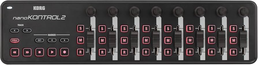
- For the KORG:
For servos and dimmer controls, depress and hold down Button “S” of the left-most channel while moving the left-most slider.
For motor (SMI and Jrk) controls, depress and hold down Button “S” of the left-most channel while moving the left-most slider.
For relay controls, press the left-most Button “S” to toggle the relay’s state.
The KORG can also be used to start and stop execution (see Playing, Pausing, and Stopping Execution).