Execution
Execution is the heart of VSA. Two main operations are performed during execution: sending of the movement commands and playing of the audio file. Both operations are performed by a real-time process. This real-time process is designed so that it executes at the same speed: whether on a 500MHz or 3GHz machine. The time is dependent on the user set frame rate.
Device Settings
From the Tools > Settings... dialog, track and device information can be specified that determines what kind of hardware VSA will control.
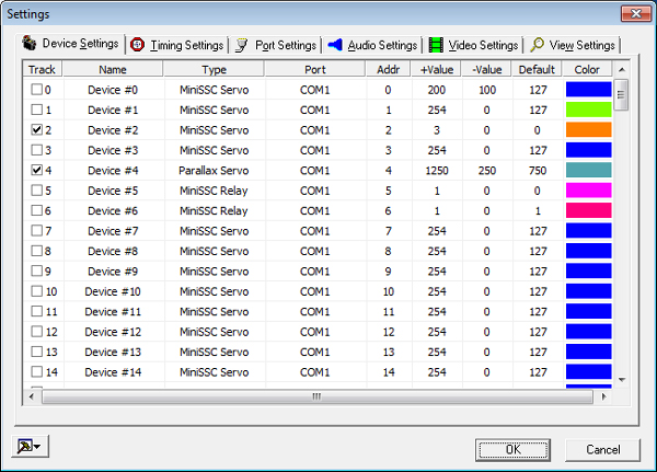
NameDouble click on the name column to specify a custom name for the device. This name will show beside the track in the Event View.TypeDouble click on the type column to choose what kind of hardware this track will control.PortDouble click on the port column to specify the port to which the device is connected. Devices with identical Protocols (see Device Types) may use the same port (except for LPT Servo and LPT Dimmer devices which may not be used with any other device). Configuring tracks with different Protocols to use the same port may result in unpredictable hardware behavior. See Choosing Audio Synchronization for advantages of using multiple serial ports. See Port settings for details on how ports are configured.AddressDouble click on the address column to specify the address for this track. The address must be valid for the type of device type chosen (see Device Types). Address do not need to correspond to the track number and two tracks should not translate to the same address. Note that a servo at address 0 on port 1 may exist with a servo at address 0 on port 2 but not another servo at address 0 on port 1.See Enabling and disabling device output and Device ranges and defaults for information about other options in the settings dialog.
ColorIf you scroll the window the right, you will see a column for setting the track’s color. Double click on the colored rectangle to pick a new color to be used for drawing tracks in the Event view and Plot view.
Device type |
Protocol |
Supported port types |
Example supported hardware |
Notes |
|---|---|---|---|---|
Phidget Servo |
Phidget |
USB |
Phidget Servo (e.g., 16x RC Servo Phidget) |
A USB VINT Hub is recommended. |
Phidget Relay |
Phidget |
USB |
Phidget DigitalOutput (e.g., 4x Isolated Solid State Relay Phidget) |
A USB VINT Hub is recommended. |
Phidget Motor |
Phidget |
USB |
Phidget DC Motor (e.g., 2x DC Motor Phidget) |
A USB VINT Hub is recommended. |
Phidget Dimmer |
Phidget |
USB |
Phidget VoltageOutput (e.g., PhidgetAnalog 4-Output) |
|
Lynxmotion Servo (optionally continuous) |
Lynxmotion |
COM |
Lynxmotion SES-V2 LSS-ADA with Smart Servos |
|
Dynamixel Servo (optionally continuous) |
Dynamixel |
COM |
Dynamixel U2D2 with supported servos |
To enable continuous rotation, set the mode to |
SSC32 Servo |
LynxMotion SSC32 |
COM, RAPU |
SSC32 |
Valid addresses 0-31. |
SSC32 Relay |
LynxMotion SSC32 |
COM, RAPU |
SSC32 |
Valid addresses 0-31. |
Pololu Maestro Servo and Pololu Maestro Relay |
Pololu |
COM |
Pololu Micro Maestro 6, Pololu Mini Maestro 12, Pololu Mini Maestro 18, Pololu Mini Maestro 24 |
|
Pololu Jrk G2 Motor |
Pololu |
COM |
Pololu Jrk 12v12, Pololu Jrk 21v3 |
|
Pololu Simple Motor Controller G2 |
Pololu G2 |
COM |
Pololu SMC G2 18v15, SMC G2 24v12, SMC G2 18v25, SMC G2 24v19 |
Use the |
Pololu Tic Stepper Motor |
Pololu |
COM |
Pololu Tic T500, Tic T834 |
This board requires a TTL serial port connection for control; it cannot be controlled via its USB interface. |
DMX Servo |
DMX |
RAPU, ENTTEC |
All DMX motor/servo mounts (e.g., Chauvet Luminary Yoke Legend 2000) |
|
DMX Relay |
DMX |
RAPU, ENTTEC |
All DMX relays |
|
DMX Dimmer |
DMX |
RAPU, ENTTEC |
All DMX dimmers (e.g. Chauvet DMX1 DMX4 Stage Dimmer 12) |
|
Legacy Devices
Some devices are no longer made or few devices support the protocol. VSA still has minimal support for these devices, but it is no longer actively maintained. Users should not use legacy devices for new designs.
Device type |
Protocol |
Supported port types |
Example supported hardware |
Notes |
|---|---|---|---|---|
BoC Servo |
DMX |
RAPU, K8062, ENTTEC |
Skulltronix Board of Chuckie (BoC) |
Each servo uses two addresses. For example, if the address is 0, the MSB is written to the first DMX address and the LSB is written to the second DMX address. |
EnduranceRC Servo |
EnduranceRC Servo |
ENRC |
EnduranceRC 25 Servo Controller |
Valid addresses 0-24. |
K108A Relay |
K108A Relay |
COM, RAPU |
K108A |
Valid addresses 0-7. |
LPT Servo |
IO Port Write |
LPT |
Custom |
The address is not used. May not be used with other LPT devices. The STROBE line is pulsed low whenever the port is updated. |
LPT Dimmer |
IO Port Write |
LPT |
Custom |
The address is not used. May not be used with other LPT devices. The STROBE line is pulsed low whenever the port is updated. |
LPT Relay |
IO Bit Write |
LPT |
K74 and custom |
The address determines the LPT bit to be controlled. The STROBE line is pulsed low whenever the port is updated. Valid addresses 0-7. |
MiniSSC Servo |
MiniSSC |
COM, RAPU |
Valid addresses 0-254. |
|
MiniSSC Relay |
MiniSSC |
COM, RAPU |
Custom |
Valid addresses 0-254. |
MiniSSC Dimmer |
MiniSSC |
COM, RAPU |
Custom |
Valid addresses 0-254. |
Parallax Servo |
Parallax |
COM, RAPU |
Parallax Servo Controller (USB), Parallax Servo Controller (Serial), and Propeller Servo Controller |
Valid addresses 0-31. |
PicoPic Servo |
PicoPic |
COM, RAPU |
PicoPic |
The zero-th address corresponds to the first servo. The board number is based on the servo number. For example, servos 0-19 will be on board 1 as servos 1-20. Servos 20-39 will be on board 2 as servos 1-20. |
PicoPic Relay |
PicoPic |
COM, RAPU |
PicoPic |
The zero-th address corresponds to the first servo. The board number is based on the servo number. For example, servos 0-19 will be on board 1 as servos 1-20. Servos 20-39 will be on board 2 as servos 1-20. |
Pololu Servo |
Pololu USB or MiniSSC |
COM, RAPU |
Pololu USB 16-Servo Controller |
Valid addresses 0-255. Not compatible with the Pololu Maestro or Jrk controllers. |
SMI Motor |
MiniSSC |
COM, RAPU |
Valid addresses 0-254. |
|
SV203 Servo |
SV203 |
COM, RAPU |
Valid addresses 0-254. |
|
SV203 Relay |
SV203 |
COM, RAPU |
Valid addresses 0-254. |
Enabling and disabling device output
In order to allow a routine to be tested for timing issues, for example, all device output can be disabled. By choosing Enable/Disable Devices from the Execution menu, by using the Enable/Disable Devices option on the right vertical toolbar, or by pressing the “s” key, the output to the devices is toggled. When the devices are enabled (default), position commands are sent to the devices. When disabled, VSA issues no execution-time commands to the devices.
Alternatively, individual tracks can be disabled from the Tools | Settings… dialog. By toggling the small check next to the track number, tracks are enabled or disabled. No data is sent to disabled devices during execution and disabled devices are not drawn in the Plot view.
Device ranges and defaults
A device’s range and default positions may be set from the Tools > Settings... dialog.
To edit the default position for a track, double click on the entry and a dialog will appear. Using the device control, select new minimum, maximum, and default positions. Note that the minimum position must be less than or equal to the maximum and that the default position must be between or equal to the maximum and minimum positions.
By choosing Reset Device Positions from the Execution menu, by using the Reset Device button on the right vertical toolbar, or by pressing the backspace key, a command is sent to all devices to reset to their default positions.
Port settings
VSA communicates to hardware through communications (serial or USB), parallel, RAPU, Velleman, and ENTTEC ports. Select Tools > Settings..., and then the Port Settings tab to alter the hardware port configuration. Parallel, Velleman, and ENTTEC ports have no user configurable parameters and are not displayed on the Port Settings tab.
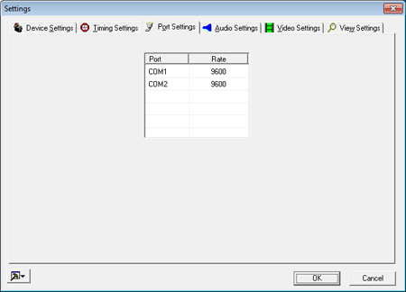
Serial Ports The system’s serial ports are detected and displayed with a user-configurable baud rate. This baud rate should be selected based on the hardware’s highest possible speed. The serial port can support a variety of devices as defined in the Device Settings.
RAPU Ports If the RAPU Manager is installed and one or more RAPU (v3-v5) is linked via USB, the RAPU can be configured as a USB serial or DMX device. The baud rate should be selected based on the hardware’s highest possible speed. The baud rate option “DMX” should be selected if the RAPU is to be used to control DMX devices. This option is not supported with the RAPU v6 and later.
Playing, Pausing, and Stopping Execution
Play/Pause/Stop all perform their respective operations during execution.
 Play may be started by choosing
 Play Allfrom theExecutionmenu, by using the shortcut on the right vertical toolbar, or by pressing the “Enter” key. Play may be paused by choosing
 Pausefrom theExecutionmenu, by using the shortcut on the right vertical toolbar, or by pressing the space bar. Play may be stopped by choosing
 Stopfrom theExecutionmenu, by using the shortcut on the right vertical toolbar, or by pressing the Escape key. Play may be looped indefinitely by choosing
 Loop Playfrom theExecutionmenu, by using the shortcut on the right vertical toolbar, or by pressing SHIFT + 2.
During play, a play cursor is displayed at the current position. Depending on the speed of the PC, the play cursor may lag behind the actual execution as graphic update is considered less important than accurate wave/event synchronization. Play status is displayed in the status bar.
If you are using a KORG nanoKONTROL2, you can also start and stop playback via the “play” and “stop” buttons. See Joystick/MIDI control for more details.
Note: At the beginning of play, all devices are reset to their user-defined default positions.
Note: If no events exist, the execution procedure will report a No Events Defined error message.
Playing with markers
Markers provide a quick means to play a small portion of a routine. Portions of the routine can be selected and isolated by using the provided marker playing tools. See Using markers for more information about how to isolate a portion of the routine.

Play to Second MarkerPlays from the beginning of the script to the stop marker.
Play Between MarkersPlays from the first marker to the second marker.
Play FramePlays the frame at the first marker.
Play from First MarkerPlays from the first marker to the end of the routine.
Both keyboard shortcuts and menu commands can be found under the Execution menu.
Caution: When play does not begin at the beginning of the routine, the devices are initialized to the positions immediately before the frame where play is to begin. As a result, devices may “jump” to positions before play is begun. This is normal and necessary, but the repositioning may occur faster than intended.
Logical design check errors
It is possible to create/edit events so that they overlap. Since two overlapping events would attempt to command the device to two different positions at the same time, this is an error condition. When any type of execution is begun, events are scanned for these types of errors.
If errors exist, a warning message will be displayed indicating that the Logical Design Check Reported Errors. Additionally, the offending events will be highlighted in red.

Command line execution
VSA routines may be executed from the command line. The following command line prototype shows the syntax:
VSA.EXE "MyVSA.VSA" /play /minimize /close
/minimizeBefore loading the routine, VSA is minimized and appears only in the task bar. VSA is not made the active window./playAfter loading the routine, VSA will begin execution./closeAfter the first execution of the routine, VSA will automatically shutdown.
The quotes need to be included to support Windows long file names. Command parameters can be used separately, but when used together, /play /minimize /close, the routine will be loaded, played, and then closed all while the application is minimized.